

I had previously used the Adafruit TFT display using my library (ported from the Adafruit Arduino library). I decided to optimize the library to improve drawing speed. The same display I use comes with a 4-wire resistive touch-screen as well. I decided to write a simple library for the touch-screen and give Protothreads a try. To incorporate all this, I thought it would be cool if I used these to make a simple game. Tic-tac-toe came to mind as a fun little demo.
I'm sure everyone's familiar with the game so I won't explain the rules there. The touch-screen is simply two resistive sheets placed on top of each other on top of the TFT screen. When it is pressed down at a given place, the two sheets make contact and a voltage divider is formed. Using the IO's and the ADC, this voltage is read in the X and Y directions to register a touch.
Here is a very good pictorial depiction of the resistive touch screen (taken from the Atmel AVR341 document):
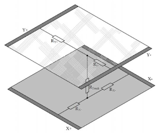
So in order to read the touch, the X+ and X- points are applied power, and one of Y+ or Y- is read to read the x-coordinate. Then Y+ and Y- are applied power and one of X+ or X- is read to read the y-coordinate. X+, X-, Y+ and Y- are connected to four GPIO pins on the PIC32 that are configured to outputs when driving the touch-screen and analog inputs when reading. Every time the IO pin switches state, a long delay is provided to allow the outputs to stabilize. Alternately, the ADC is significantly slowed down to negate effects of capacitive charging by high source impedance. The library is written in the form of a simple state machine cycling through its states every few milliseconds, decided by the application calling the library functions. In my application, I use 5 milliseconds.
To organize the game, I've made use of the Protothreads threading library. Protothreads is a very light-weight, stackless, threading library written entirely as C macros by Adam Dunkels. Bruce Land has ported Protothreads over for the PIC32. You can find more details on his excellent site: http://people.ece.cornell.edu/land/courses/ece4760//PIC32/index_Protothreads.html
There are two main executing threads, one is the main game thread and the other is a clock thread that keeps track of, and displays, time since the program was started. There is a third thread used to retrieve touch information. It is spawned by the main game thread when touch input is required. The main Protothreads functions (macros) I've made use of are:
PT_setup()
PT_INIT()
PT_SCHEDULE()
PT_SPAWN()
PT_WAIT_UNTIL()
PT_YIELD_TIME_msec()
PT_GET_TIME()
Pin connections:
BL (backlight): I left it unconnected, but you can connect it to 3.3V for backlight.
SCK: connected to RB14 on the PIC
MISO: left unconnected, since I'm not reading anything from the screen
MOSI: connected to RB11 on the PIC
CS: connected to RB1 on the PIC
SDCS: left unconnected as I'm not using the microSD card for this
RST: connected to RB2 on the PIC
D/C: connected to RB0 on the PIC
X+: connected to RA4 on the PIC
X-: connected to RB13 on the PIC
Y+: connected to RB5 on the PIC
Y-: connected to RB15 on the PIC
VIN: connected to 3.3V supply
GND: connected to gnd
Here is a demo of the game:
Besides the game itself, you can see the running clock on the bottom left right above the players' scores. To the bottom right you can see a flickering circle that is either green or red, depending on if it's player 1 or 2's turn, respectively. Once the game is over, you have the option of playing another game while score is being tracked.
Here is a link to the MPLABX project with all required header and source files:
https://drive.google.com/file/d/0B4SoPFPRNziHbURwVWVSN1c3VVE/view?usp=sharing
I have commented the code to make it fairly self-explanatory. If you have doubts or questions about anything, let me know and I'll add more detail. Let me know what you think!
Comments
Post a Comment