CASE STUDY, IMPLEMENTATION AND EXAMPLES OF I2C
2.) Some devices are masters – they generate bus clock and initiate communication on the bus, other devices are slaves and respond to the commands on the bus. In order to communicate with specific device, each slave device must have an address which is unique on the bus.
3) Physically, the I²C bus consists of the 2 active wires SDA and SCL and a ground connection. The active wires are both bi-directional.

4) Start Stop Conditions and Data Transfer - Each I2C command initiated by master device starts with a START condition and ends with a STOP condition. For both conditions SCL has to be high. A high to low transition of SDA is considered as START and a low to high transition as STOP.
Data on the I2C bus is transferred in 8-bit packets (bytes). There is no limitation on the number of bytes, however, each byte must be followed by an Acknowledge bit. This bit signals whether the device is ready to proceed with the next byte.

i)First, the master will issue a START condition. All ICs on the bus will listen to the bus for incoming data.
ii)Then the master sends the ADDRESS of the device it wants to access, along with an indication whether the access is a Read or Write operation. Having received the address, all IC’s will compare it with their own address.
iii)If it doesn't match, they simply wait until the bus is released by the stop condition. If the address matches, however, the chip will produce a response called the ACKNOWLEDGE signal.Once the master receives the acknowledge, it can start transmitting or receiving DATA.

CASE STUDY AND IMPLEMENTATION
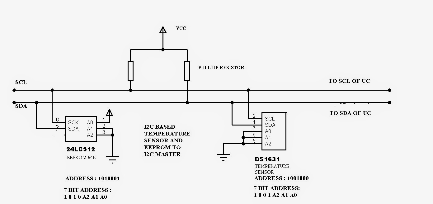
Consider the following example, where it is desired to read the temperature from DS1631 Temperature Sensor and store it to 24LC512 EEPROM using a PIC Microcontroller.


DS1631:
The master needs to send 51H to convert temperature into 12bit data which is stored in TH and TL of DS1631. To read the temperature, AAH needs to be sent.


24LC512:
For byte write operation, two bytes of addresses are required to select one out of 65536 locations in the EEPROM. Master provides these two address bytes after the control byte has been sent. 24LC512 responds with an acknowledge pulse after receiving each address byte. Master then sends a byte of data to be written in to the memory0. Upon receipt of this data, 24LC512 sends an acknowledge pulse.

IMPLEMENTATION USING PIC 16F882 MICROCONTROLLER
1) Initialize I2C in master mode(SSPCON1), set speed to 100kbps (SSPADD)
2) The following functions are required :
a) I2Cstart (set SEN bit) b) I2Crepeatedstart (set RSEN bit) c) I2Cstop(set PEN bit)
d) I2Cread(read data from SSPBUF) e)I2Cwrite(write data to SSPBUF) f)I2Cwait()
3) Start I2C. Write 1001000(0) i.e. master will write to DS1631.
4) Write 51H to DS1631 and free the bus(i.e Stop Condition)
5) Write Start condition again, write 1001000(0) i.e. select DS1631 in write mode and write AAH to it.
6) Execute Reapeated Start conditon. Select DS1631 again but in read mode(i.e. write 1001000(1)).
7) Read two bytes of data and send ACK and NACK and then stop.
8)Now, start I2C again, write 1010001(0) i.e. master will write to 24LC512 EEPROM.
9)Write the desired address (2 bytes) say 1000H and then write the temperature value acquired from DS1631. Every 8 bit is written after ACK is recieved from slave.
10) Stop condition on I2C bus. Repeat the steps in a loop and increment the EEPROM address values to log temperature.
Examples of I2C Devices

-ABHIRAJ NAMBIAR
BE-Q ROLL NO- 48
Comments
Post a Comment