
Condenser Pre Amplifier LM 1458


This is a simple preamplifier circuit for electret condenser microphone.
using a LM1458 dual op amp IC. The circuit takes the audio signal rom the condenser microphone and amplifier it, so you can use the microphone as the input to some device which wouldn’t normally accept microphone level signals .

Condenser Pre Amplifier


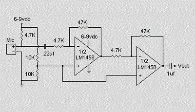
Schematic Circuit of Microphone Electret

Condenser Pre Amplifier


The circuit requires a 6-9 volt supply. Output of the microphone amplifier can be made variable by connecting a 10kΩ potentiometer . Circuit’s gain can be increased by men perbesar the value of 47K, depending on the input sensitivity of the main amplifier system. The microphone should be housed in a small round enclosure.


List componet of condenser pre-amp mic circuit

Q1,Q2    : LM1458 Op-Amp

R1,R2,R3 : 4.7k ohm resistor

R4, R5   : 10k ohm resistor

R6,R7    : 47k ohm resistor

C1,      : 0.22uF ceramic capacitor

C2       : 1uF ceramic capacitor


Absolute maximum ratings of LM 1458 IC

Supply Voltage               :  ±18V

Power Dissipation            : 400 mW

Differential Input Voltage   : ±30V

Input Voltage                : ±15V

Output Short-Circuit Duration: Continuous

Operating Temperature Range  : 0°C to +70°C

Storage Temperature Range    : −65°C to +150°C

Lead Temperature             :(Soldering, 10 sec.) 260°C

Comments

Popular posts from this blog

Digital Fan Regulator Circuit Diagram

This is the project of Digital Fan Regulator Circuit diagram. The circuit presented here can be used to control the speed of  fans using induction motor. The speed control is nonlinear, i.e. in steps. The current step number is displayed on a 7-segment display. Speed can be varied over a wide range because the circuit can alter the voltage applied to the fan motor from 130V to 230V RMS in a maximum of seven steps.  The triac used in the final stage is fired at different angles to get different voltage outputs by applying short-dura-tion current pulses at its gate. For this pur-pose a UJT relax-ation oscillator is used that outputs sawtooth waveform. This waveform is coupled to the gate of the triac through an optocoupler (MOC3011) that has a triac driver output stage.  Pedestal voltage control is used for varying the firing angle of the triac. The power supply for the relaxation oscillator is derived from the rectified mains via 10-kilo-ohm, 10W series dropping/limit-ing...

24 Hour Timer

Description: These two circuits are multi-range timers offering periods of up to 24 hours and beyond. Both are essentially the same. The main difference is that when the time runs out, Version 1 energizes the relay and Version 2 de-energizes it. The first uses less power while the timer is running; and the second uses less power after the timer stops. Pick the one that best suits your application. Notes: The Cmos 4060 is a 14 bit binary counter with a built in oscillator. The oscillator consists of the two inverters connected to Pins 9, 10 & 11; and its frequency is set by R3, R4 & C3.The green Led flashes while the oscillator is running: and the IC counts the number of oscillations. Although it's a 14 bit counter, not all of the bits are accessible. Those that can be reached are shown on the drawing. By adjusting the frequency of the oscillator you can set the length of time it takes for any given output to go high. This output then switches the transistor; which in turn o...

Using the SG3525 PWM Controller Explanation and Example Circuit Diagram Schematic of Push Pull Converter

PWM is used in all sorts of power control and converter circuits. Some common examples include motor control, DC-DC converters, DC-AC inverters and lamp dimmers. There are numerous PWM controllers available that make the use and application of PWM quite easy. One of the most popular of such controllers is the versatile and ubiquitous SG3525 produced by multiple manufacturers – ST Microelectronics, Fairchild Semiconductors, On Semiconductors, to name a few. SG3525 is used extensively in DC-DC converters, DC-AC inverters, home UPS systems, solar inverters, power supplies, battery chargers and numerous other applications. With proper understanding, you can soon start using SG3525 yourself in such applications or any other application really that demands PWM control. Before going on to the description and application, let’s first take a look at the block diagram and the pin layout. Pins 1 (Inverting Input) and 2 (Non Inverting Input) are the inputs to the on-board error amplifier. If you a...