
OVER LIGHT SENSOR ALARM CIRCUIT


OVER LIGHT DETECTOR


Here i am going to Introduce you an Excess light Detector or sensor circuit.

The sensing component used in this circuit is LDR (Light Dependent Resistor).

LDRs are sensitive, inexpensive and readily available device. They posses good power and voltage handling capacity similar to an ordinary resistor.


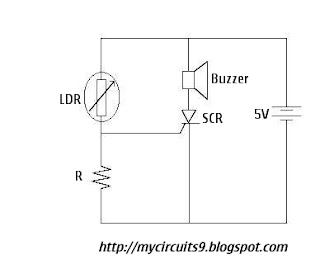
CIRCUIT DIAGRAM OF OVER LIGHT DETECTOR


simple over light alarm circuit diagram


Components required to wire up this circuit


1. LDR
2. R - 1K
3. SCR
4. Buzzer
5. 5V BATTERY


WORKING PRINCIPLE OF OVER LIGHT DETECTOR


The LDR is a variable resistor whose resistance decreases with increase in light intensity. When the light falling on an LDR has normal intensity, its Resistance is large enough and the voltage across R is insufficient to trigger the SCR. However, when light falling on LDR is of large intensity, the Resistance of LDR falls and voltage drop across R becames large enough to trigger the SCR. Consequently the buzzer sounds the alarm. It may be noted that if the strong light disappears the buzzer continues to sound the alarm. It is because once the SCR is triggered the gate loses its control.

You can use this circuit as LIGHTNING DETECTOR AND ALARM


Back To HOME For More Projects


Comments

Popular posts from this blog

Digital Fan Regulator Circuit Diagram

This is the project of Digital Fan Regulator Circuit diagram. The circuit presented here can be used to control the speed of  fans using induction motor. The speed control is nonlinear, i.e. in steps. The current step number is displayed on a 7-segment display. Speed can be varied over a wide range because the circuit can alter the voltage applied to the fan motor from 130V to 230V RMS in a maximum of seven steps.  The triac used in the final stage is fired at different angles to get different voltage outputs by applying short-dura-tion current pulses at its gate. For this pur-pose a UJT relax-ation oscillator is used that outputs sawtooth waveform. This waveform is coupled to the gate of the triac through an optocoupler (MOC3011) that has a triac driver output stage.  Pedestal voltage control is used for varying the firing angle of the triac. The power supply for the relaxation oscillator is derived from the rectified mains via 10-kilo-ohm, 10W series dropping/limit-ing resistor R2. 

Home automation with Telegram BOT

The project I’m going to describe today it’s a sort of proof of concept that will demonstrate the possibility to remote control sensors and actuators (for example a couple of relays) via Telegram. Telegram is an instant messaging application, similar to the famous Whatsapp. Last June, the Telegram developers announced that a new set of APIs were available to develop bots. [ ]

Circuit Cat And Dog Repellent

The electronic dog repellent circuit diagram below is a high output ultrasonic transmitter which is primarily intended to act as a dog and cat repeller, which can be used individuals to act as a deterrent against some animals. It should NOT be relied upon as a defence against aggressive dogs but it may help distract them or encourage them to go away and do not consider this as an electronic pest repeller. The ultrasonic dog repellant uses a standard 555 timer IC1 set up as an oscillator using a single RC network to give a 40 kHz square wave with equal mark/space ratio. This frequency is above the hearing threshold for humans but is known to be irritating frequency for dog and cats. Since the maximum current that a 555 timer can supply is 200mA an amplifier stage was required so a high-power H-bridge network was devised, formed by 4 transistors TR1 to TR4. A second timer IC2 forms a buffer amplifier that feeds one input of the H-bridge driver, with an inverted waveform to that of IC1 ou