
OP AMP BASED MONOSTABLE MULTIVIBRATOR 741


CIRCUIT DIAGRAM OF OP AMP BASED MONOSTABLE MULTIVIBRATOR (741 IC)


Monostable op amp circuit diagram


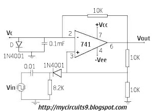
MONOSTABLE MULTIVIBRATOR USING OP AMP 741

Monostable multivibrator is also called as One Shot Multivibrator. It has a Stable State and a Quasi-Stable State. The circuit remains in stable state until a triggering signal is applied to its input. After getting the triggering signal the output transit from stable to Quasi-stable state and return back after a time period. So a Single Pulse is generated for single Trigger.


Consider the instant at which the output Vo=+Vsat. At that time diode D1 damps the Capacitor voltage, Vc at 0.7V. Feedback voltage is +βVsat at Non-Inverting terminal. When the negative trigger is applied, the potential at Non-Inverting terminal becomes less than 0.7v the output switches to -Vsat, which makes the diode more negative than -βVsat. Comparator switches back to +Vsat. The Capacitor C starts charging to +Vsat through R until Vc reaches 0.7v and C becomes damped to 0.7v.
The pulse width is given by T=RC*ln(1/1-β).


You may also Like:-
Monostable Multivibrator Tutorial

Comments

Popular posts from this blog

Digital Fan Regulator Circuit Diagram

This is the project of Digital Fan Regulator Circuit diagram. The circuit presented here can be used to control the speed of  fans using induction motor. The speed control is nonlinear, i.e. in steps. The current step number is displayed on a 7-segment display. Speed can be varied over a wide range because the circuit can alter the voltage applied to the fan motor from 130V to 230V RMS in a maximum of seven steps.  The triac used in the final stage is fired at different angles to get different voltage outputs by applying short-dura-tion current pulses at its gate. For this pur-pose a UJT relax-ation oscillator is used that outputs sawtooth waveform. This waveform is coupled to the gate of the triac through an optocoupler (MOC3011) that has a triac driver output stage.  Pedestal voltage control is used for varying the firing angle of the triac. The power supply for the relaxation oscillator is derived from the rectified mains via 10-kilo-ohm, 10W series dropping/limit-ing resistor R2. 

Home automation with Telegram BOT

The project I’m going to describe today it’s a sort of proof of concept that will demonstrate the possibility to remote control sensors and actuators (for example a couple of relays) via Telegram. Telegram is an instant messaging application, similar to the famous Whatsapp. Last June, the Telegram developers announced that a new set of APIs were available to develop bots. [ ]

Circuit Cat And Dog Repellent

The electronic dog repellent circuit diagram below is a high output ultrasonic transmitter which is primarily intended to act as a dog and cat repeller, which can be used individuals to act as a deterrent against some animals. It should NOT be relied upon as a defence against aggressive dogs but it may help distract them or encourage them to go away and do not consider this as an electronic pest repeller. The ultrasonic dog repellant uses a standard 555 timer IC1 set up as an oscillator using a single RC network to give a 40 kHz square wave with equal mark/space ratio. This frequency is above the hearing threshold for humans but is known to be irritating frequency for dog and cats. Since the maximum current that a 555 timer can supply is 200mA an amplifier stage was required so a high-power H-bridge network was devised, formed by 4 transistors TR1 to TR4. A second timer IC2 forms a buffer amplifier that feeds one input of the H-bridge driver, with an inverted waveform to that of IC1 ou