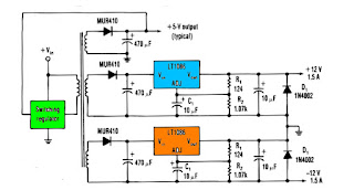
One way to provide good negative-voltage regulation is with a low-drop-out positive-voltage regulator operating from a well-isolated secondary winding of a switch-mode circuit transformer. The technique works with low-dropout types.Under all loading conditions , the minimum voltage difference between the regulator Vin and Vout pins must be at least 1.5V , IC LT1086 low-dropout voltage. If this requirement isn't met, the output falls out of regulation. Two programming resistors, R1 and R2, set the output voltage 12V, and the IC LT1086 servo the voltage between the output and its adjusting terminals to 1.25V. Capacitor C1 improves ripple rejection, and protection diode D1 eliminates common-load problems.Since a secondary winding is galvanically isolated , a regulator 12V output can be referenced to ground. Therefore , in the case of a negative-voltage output , the positive-voltage terminal of the regulator connects to ground , and the 12V output comes off the anode of D1. The Vin terminal floats at 1.5V ore above ground.
This is the project of Digital Fan Regulator Circuit diagram. The circuit presented here can be used to control the speed of fans using induction motor. The speed control is nonlinear, i.e. in steps. The current step number is displayed on a 7-segment display. Speed can be varied over a wide range because the circuit can alter the voltage applied to the fan motor from 130V to 230V RMS in a maximum of seven steps. The triac used in the final stage is fired at different angles to get different voltage outputs by applying short-dura-tion current pulses at its gate. For this pur-pose a UJT relax-ation oscillator is used that outputs sawtooth waveform. This waveform is coupled to the gate of the triac through an optocoupler (MOC3011) that has a triac driver output stage. Pedestal voltage control is used for varying the firing angle of the triac. The power supply for the relaxation oscillator is derived from the rectified mains via 10-kilo-ohm, 10W series dropping/limit-ing...

Comments
Post a Comment